I built this enclosure when the STM32 dev board stopped being a desk object and started becoming a field-test device.
At the start, the question was whether the STM32 board, firmware, and external sensor wiring worked at all. Once the device moved toward transport and field testing, the question became more practical: can I carry this board, power it, reflash it, reset it, and place it in a test setup without treating it like a fragile bench-only assembly?
That is what this print was for.
This post is not a polished product-enclosure guide. It is a set of engineering notes from building a functional prototype enclosure for the STM32 B-L475E-IOT01A2. The focus is the board-side design process: what I checked first, which constraints mattered, how the official documentation helped, and what I would recommend to someone designing a similar enclosure at a different stage of their own journey.
Context for this prototype
This enclosure work sits inside a broader device and field-demo path:
- The board is part of a three-device STM32 field setup.
- The wider room-health device path is shown in the STM32 room monitoring case study.
The enclosure itself was not about making the device look finished. It was about giving the STM32 board a better mechanical boundary for transport, handling, and service access during functional testing.
The current print is a board enclosure for the STM32 prototype: enough protection for transport and testing, while still keeping the board visible and accessible.
The design inputs I used first
Before drawing enclosure walls, I needed reliable inputs for the board and the parts around it.
The starting references were:
- The official ST product page for the B-L475E-IOT01A Discovery kit.
- The UM2153 user manual.
- The DFRobot Gravity SCD41 product page.
Those links mattered because they gave me the baseline for:
- Board outline and connector locations.
- Button positions and access needs.
- Which USB ports had to stay reachable.
- How much vertical clearance the board and shell needed.
- The approximate size and mechanical nature of the external sensor module.
For the board itself, the user manual mattered more than any early CAD guess because it is the quickest way to sanity-check connector placement, button access, and the general board boundary before printing. For the sensor side, the documentation was useful mostly to remind me that a CO2 sensor has different mechanical needs from a board-protection enclosure.
I still checked the real hardware on the desk. That is important. Documentation gets you close, but the actual enclosure decisions usually come from combining documentation with hands-on fit checking:
- Plug the real cables in.
- Measure the real board with calipers if possible.
- Note which connectors you actually use during testing.
- Confirm what your hands need to reach during reset or reflash.
That final step is where a functional prototype enclosure usually stops being generic.
What I wanted this prototype enclosure to do
The design goal was narrow on purpose. I wanted one print that would make the STM32 board easier to use in the next stage of testing.
The enclosure had to:
- Protect the board during transport.
- Keep both micro USB ports usable.
- Leave reset and user-button interaction practical.
- Preserve some header and pin access for debugging.
- Be easy to reprint after dimension mistakes.
- Avoid turning the board into something that had to be disassembled for every small change.
What I did not optimize first:
- Perfect cosmetic finish.
- Final mounting strategy.
- Sealed environmental protection.
- Product-style industrial design.
That tradeoff was intentional. For functional prototype work, it is usually better to build the enclosure around the highest-friction real tasks first: carrying, connecting, resetting, debugging, and reprinting.
How those constraints turned into the print
The current design is a simple two-piece board enclosure.
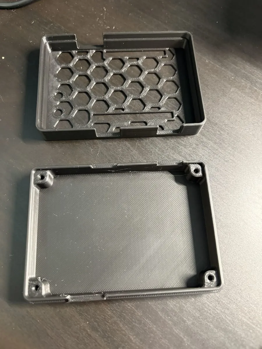
The two-piece layout kept the print simple: top shell, base, and straightforward internal posts rather than a more elaborate mechanical system.
The specific choices were practical:
- A top shell that protects the board while still letting me visually inspect it quickly.
- A base with simple support points instead of a more complicated internal structure.
- Side openings for the ports and access points I knew I would keep using.
- A geometry simple enough to print, test, adjust, and print again.
This is also why I did not aim for a closed polished case. A test-stage enclosure is often better when it still behaves like an engineering tool instead of pretending it is already a finished product.
The checks that mattered before final assembly
The most important fit test was not the shell on its own. It was the shell relative to the board, plugs, and debugging workflow.
The fit check mattered more than the render in my head. The useful question was whether the actual board, ports, and cable paths still made sense once the shell existed.
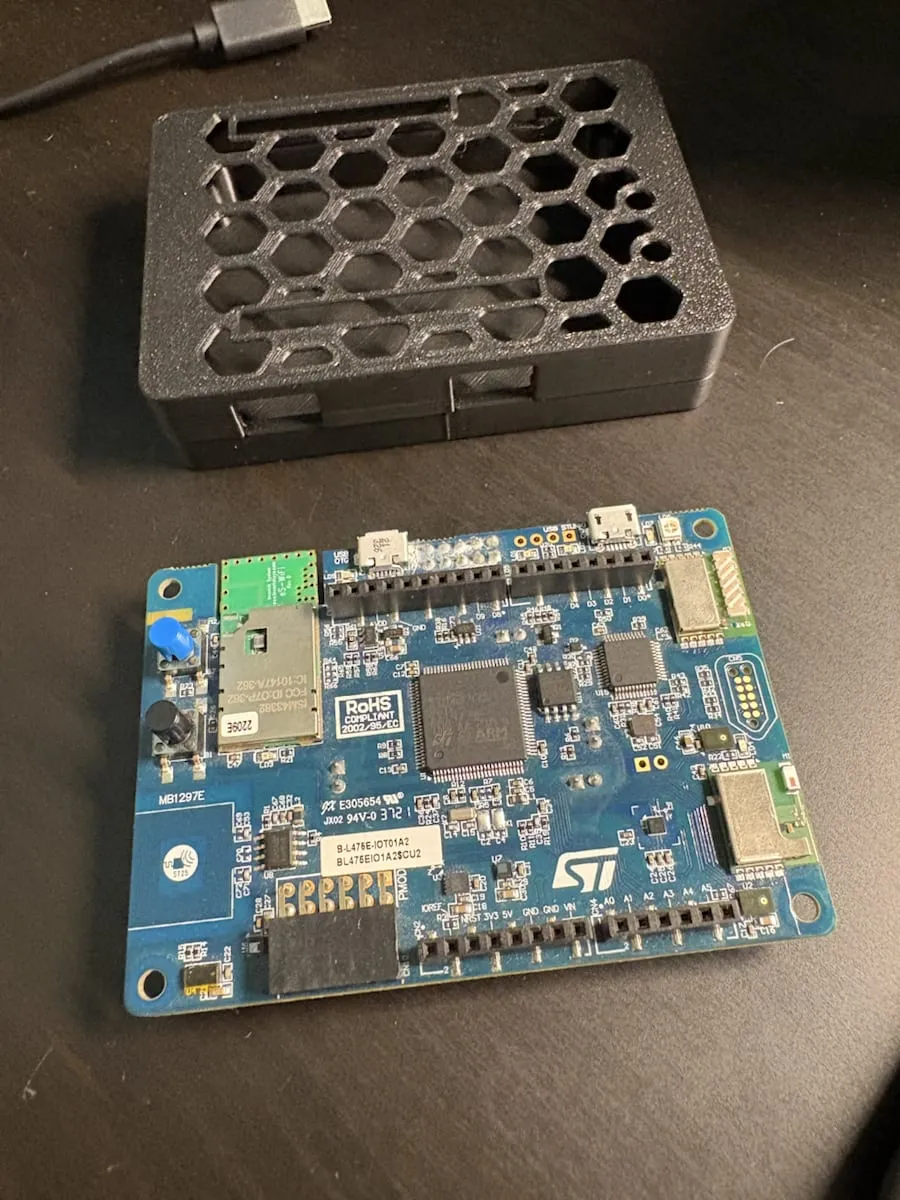
Before calling the print usable, I checked:
- Could the STM32 board drop into the enclosure without awkward force?
- Could the USB connectors still be inserted cleanly?
- Were the buttons and edge features still reachable?
- Could I still access the pins I was likely to touch during testing?
- Would a minor mistake be easy to fix with a reprint?
Those checks sound simple, but they are the difference between a case that looks right and a case that actually reduces friction.
Service access mattered more than appearance
This part of the design process is easy to underestimate when the board still lives on your desk. Once you start carrying it around, service access becomes part of the enclosure spec whether you planned for it or not.
One side of the enclosure keeps header access available:
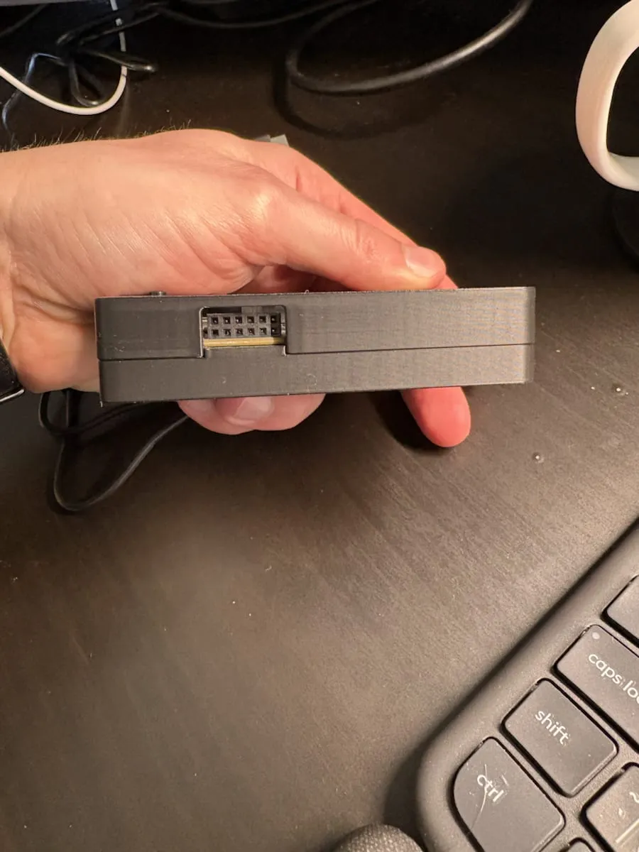
I wanted the board protected, but I did not want every pin-related check to require opening the whole enclosure.
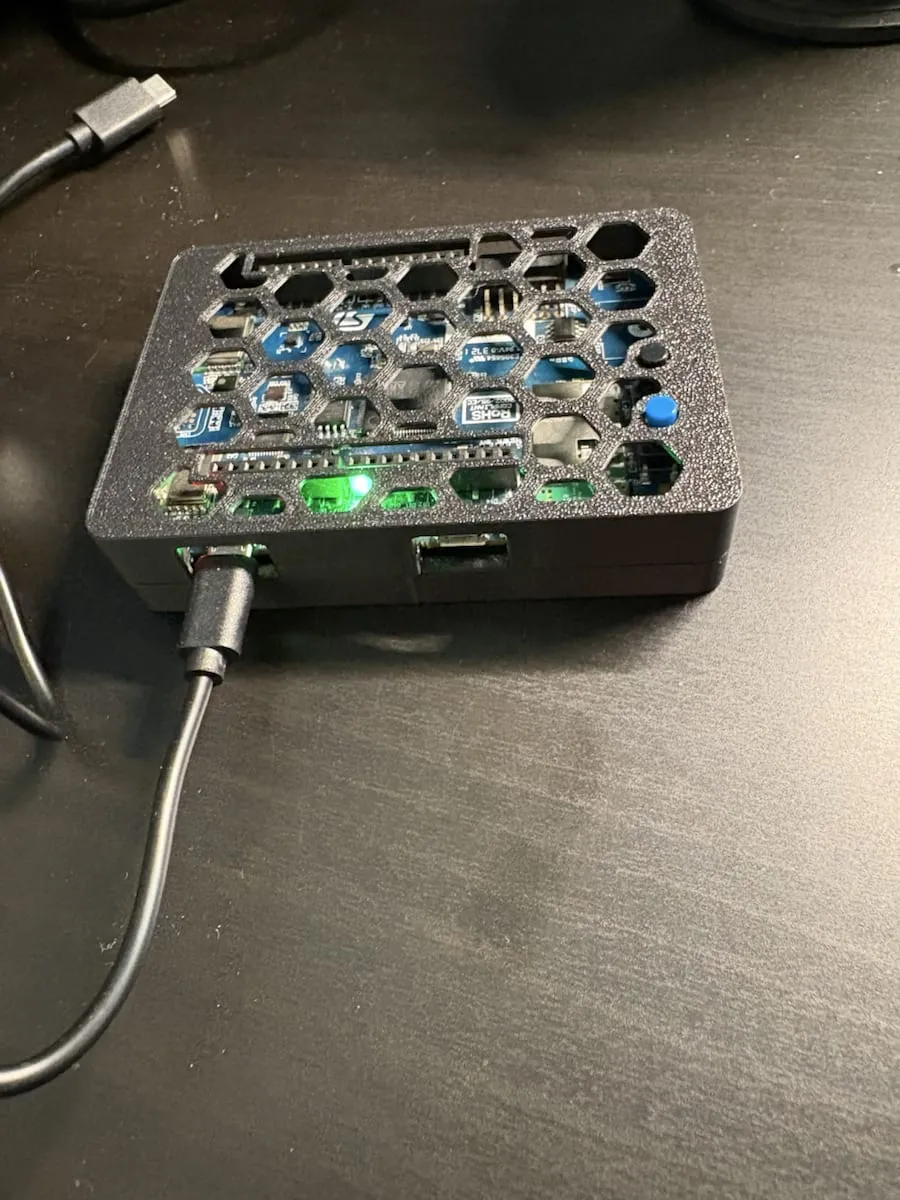
The opposite side keeps both micro USB ports exposed:
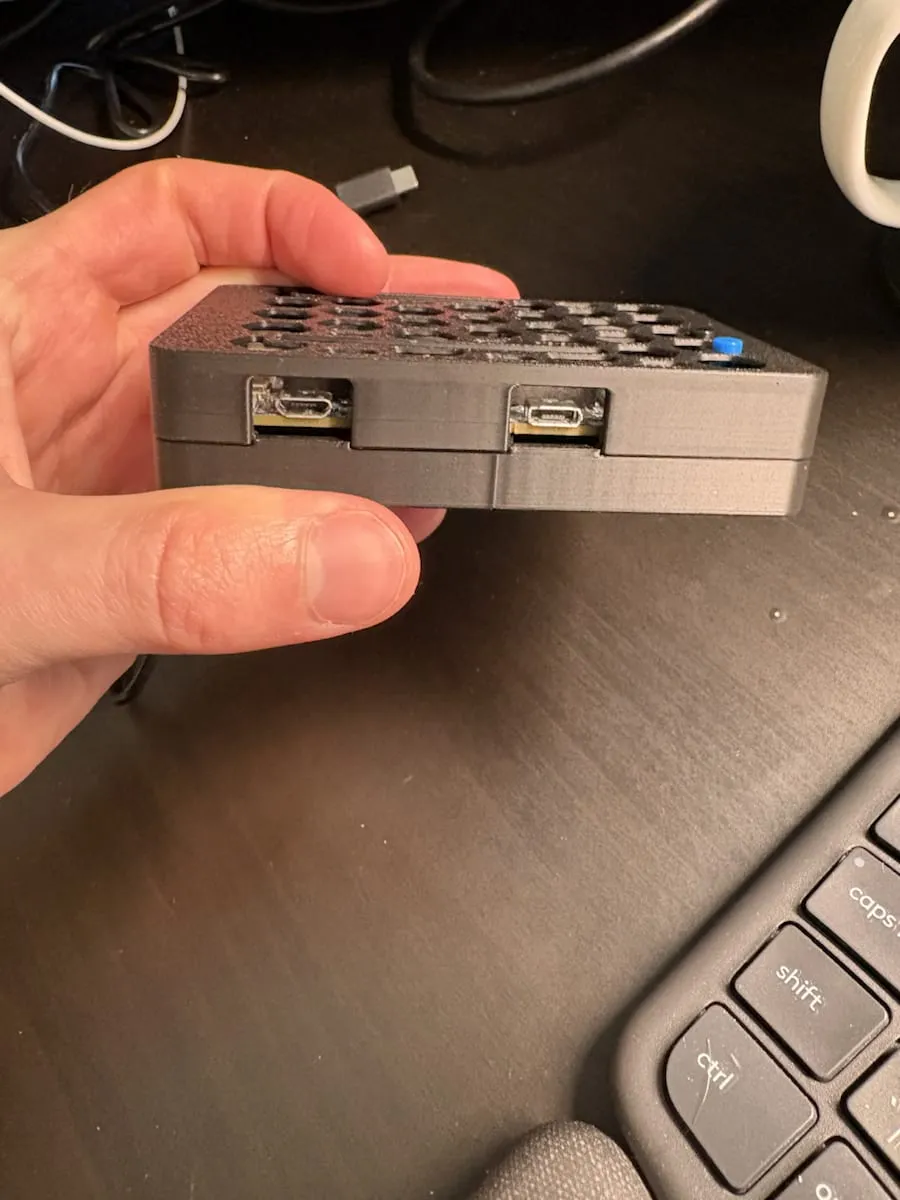
This matters during prototype work because powering, flashing, and debugging tend to happen more often than the first CAD idea suggests.
This was one of the strongest design lessons in the print: if you expect repeated firmware work, repeated resets, or repeated measurement checks, then service access is not a nice-to-have feature. It is one of the core requirements of the enclosure.
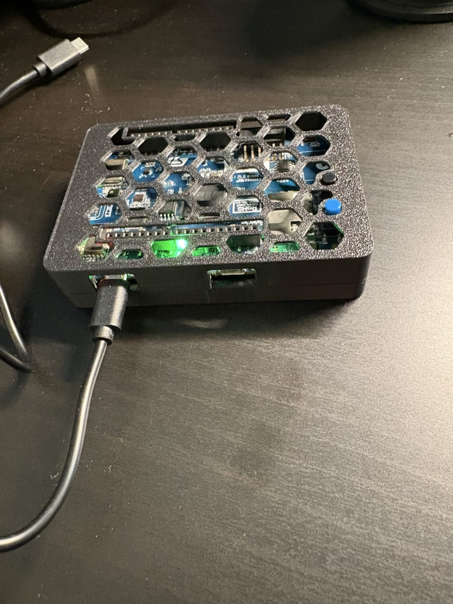
Why I kept the top open and inspectable
The vented top pattern was not mainly about aesthetics. It helped keep the board visually inspectable and stopped the enclosure from feeling like a sealed black box during early testing.
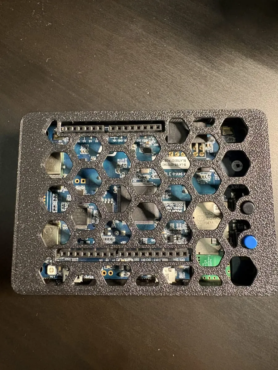
The top pattern made it easier to inspect the board state quickly while still giving the prototype a much better mechanical boundary than an exposed bare board.
That kind of decision depends on stage:
- At bench stage, you may want even more openness and faster access.
- At field-test stage, some protection and quicker handling start to matter more.
- At deployment stage, you usually need to think harder about ingress, mounting, sensor isolation, and long-term strain relief.
That is why I would encourage other builders not to copy an enclosure blindly. The right print depends on where you are in the lifecycle.
A smaller note about the external SCD41 sensor
The SCD41 is part of the system, but it is not the main story of this enclosure.
In this prototype, the SCD41 is still an external wired module. I intentionally did not package it inside this STM32 enclosure because a CO2 sensor needs its own mechanical thinking:
- Airflow path.
- Exposure to room air.
- Distance from heat sources.
- Protection from accidental contact.
- Potentially a separate vent geometry from the board housing.
So for this stage, the board enclosure was solved first. The sensor housing should be a separate, sensor-specific design problem, not an afterthought squeezed into the STM32 shell.
What I would suggest to someone designing their own enclosure
If you are building your own dev-board enclosure, I would start with these questions:
- What real task is the enclosure supposed to improve right now: transport, handling, mounting, service access, or environmental protection?
- Which ports, buttons, and debug paths do you still need every day?
- Which dimensions come from official documentation, and which ones still need measuring on the actual hardware?
- What is the simplest print you could make that solves the current friction without overcommitting to a final design?
For a functional prototype enclosure, that usually leads to better outcomes than designing for visual polish too early.
Why this stage was worth doing
This print did not finish the device. It made the next round of testing more realistic.
That was enough.
The board became easier to transport, easier to place, easier to connect, and easier to live with during field testing. That is often the real value of a prototype enclosure: not that it looks finished, but that it removes enough mechanical friction for the rest of the engineering work to move faster.
Next step
If you are designing your first functional prototype enclosure, start by protecting the board and preserving the service workflow you actually use.
The most useful early enclosure is often the one that makes transport, reset, reflashing, and fit checking easier. Sensor-specific mechanics, mounting details, and product polish can come later once the next stage of testing shows what is really worth locking in.