Most small IoT demos look good as long as the devices stay close to the laptop, the Wi-Fi stays friendly, and nobody asks what happens once telemetry has to cross a real building boundary.
That is exactly why I am working on the next field-demo step now.
I have not built this radio demo yet. This post is a design note for the setup I am bringing to life next: a three-device STM32 demo where two B-L475E-IOT01A2 nodes transmit over 868 MHz, a third board receives the radio traffic, and that receiver is connected by serial cable to a Raspberry Pi 5 that collects the telemetry for the wider gateway path.
The point is not to replace every Wi-Fi-based setup. The point is to prove a more realistic telemetry collection pattern when the useful device position is farther away, behind more walls, or simply outside the part of the building where Wi-Fi is easiest.
If you want the immediate context behind this next step, the closest Combotto references are the earlier three-device Raspberry Pi gateway field demo, the move toward a more realistic Raspberry Pi 5 gateway runtime, and the STM32 enclosure field-testing notes that helped move the hardware from desk setup toward something easier to carry and place.
The 868 MHz demo I want to build
The topology I want to test is intentionally simple:
- Two STM32
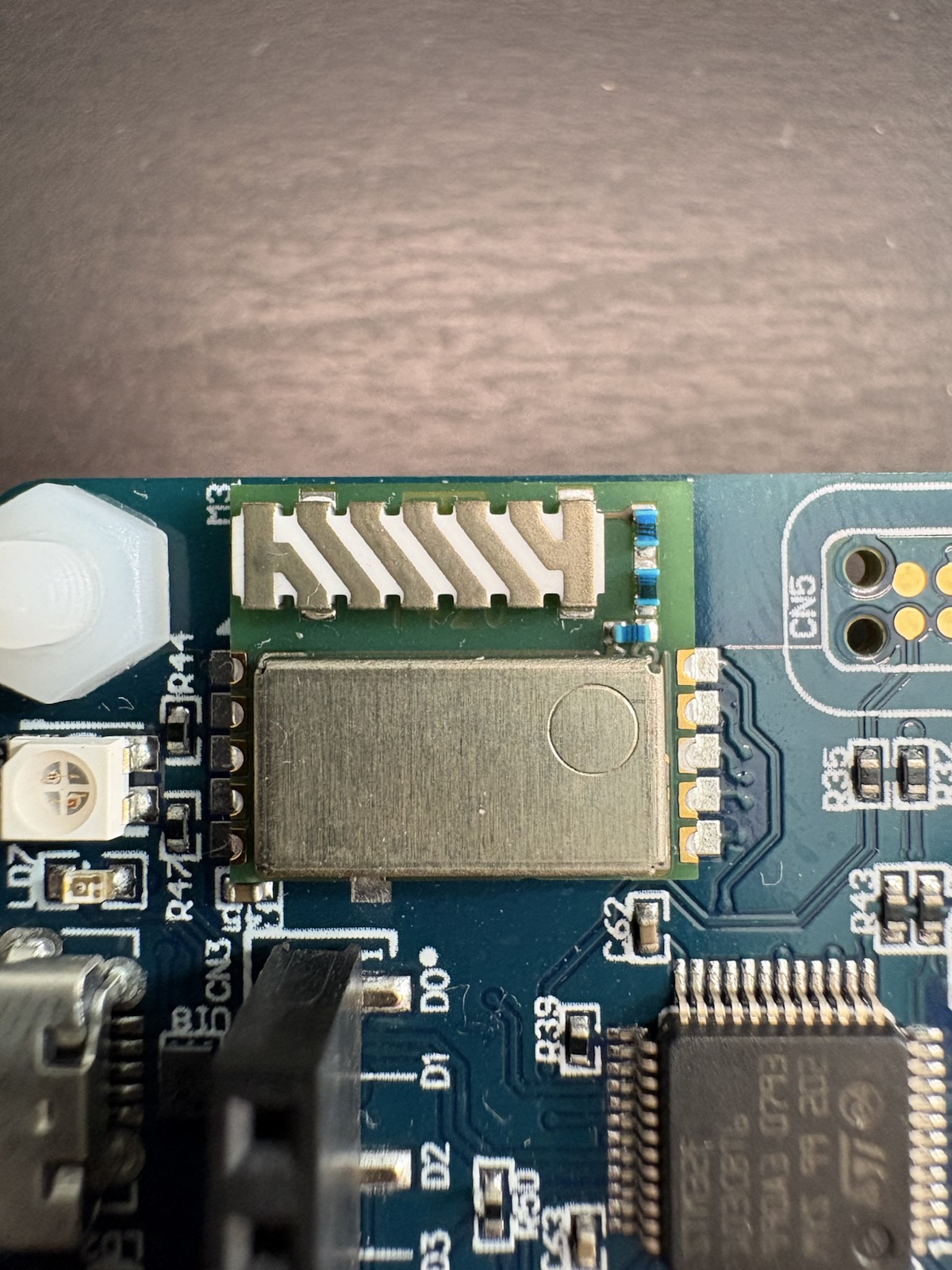
B-L475E-IOT01A2devices fitted withSPSGRF-868radios and868 MHztuned antennas acting as telemetry transmitters. - One STM32 receiver listening for that radio traffic.
- A serial connection from the receiver into a
Raspberry Pi 5. - The Raspberry Pi acting as the collection point for logging, forwarding, inspection, and later gateway-side experiments.
The diagrams below are still planning diagrams, not evidence from a finished field run. I am using them to make the intended boundaries and flow explicit before the physical demo is built.
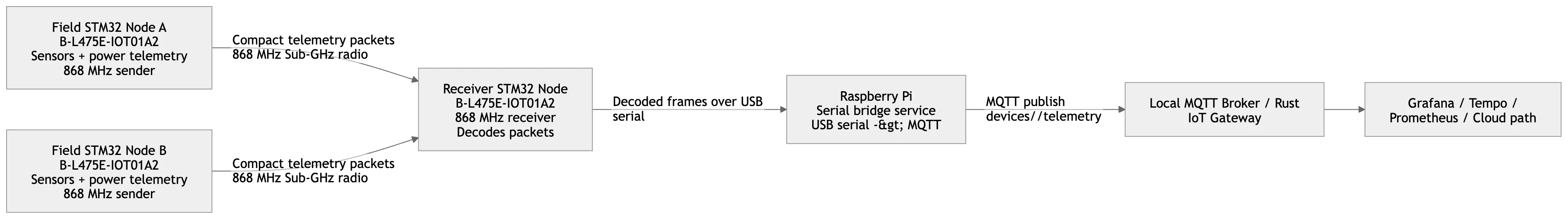
A compact view of the intended path: two STM32 field nodes publish telemetry over 868 MHz, one STM32 receiver decodes the packets, and the Raspberry Pi 5 bridges them into the wider gateway and monitoring path.
That split matters. It keeps the field nodes focused on sensor collection and radio transport while the Raspberry Pi carries the heavier runtime job: timestamps, buffering, logs, and whatever bridge logic is needed to move the incoming packets into the rest of the telemetry flow.
The current three-device Raspberry Pi setup is already useful as a baseline. This next version should extend that setup into a radio-first path that can reach farther than Wi-Fi usually can in awkward field placements.
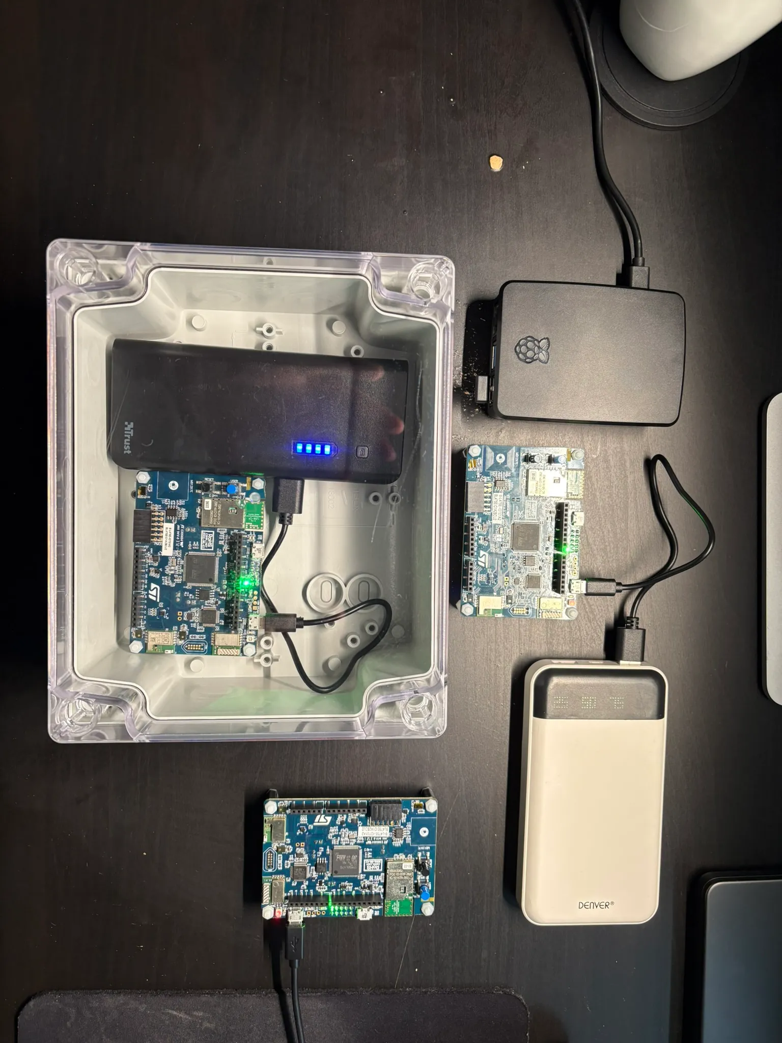
This is the current wider field setup that the radio-first version will build on: Raspberry Pi 5, power, and the broader multi-device demo context before the 868 MHz path is layered in.
Why 868 MHz is the useful next step
Wi-Fi is convenient, especially during early development. It is easy to inspect, quick to reconfigure, and good enough for many first demos.
But Wi-Fi also makes certain field problems too easy to ignore:
- Access-point coverage is uneven across real buildings.
- Device placement often becomes “where the Wi-Fi works” instead of “where the telemetry matters.”
- Wall, floor, cabinet, and utility-room boundaries can weaken the signal long before the device reaches the interesting part of the environment.
- The setup starts depending on local network conditions that are not actually part of the telemetry problem you want to study.
That is why I want a sub-GHz path in the demo.
The value is not abstract range marketing. The value is being able to place transmitters deeper in or around a building and still keep the telemetry collection path believable. If that works cleanly, the demo becomes much more useful for building-side monitoring, harder-to-reach placements, and later audit discussions about radio boundaries versus Wi-Fi boundaries.
For the technical baseline, the most useful official references I am working from are the ST board page for the B-L475E-IOT01A, the ST product page for the SPSGRF module family, and ST’s broader Sub-1 GHz product documentation hub, which collects the datasheet, integration guidance, and application notes around this radio family.
Why keep the receiver wired to a Raspberry Pi 5
The receiver-to-Pi serial link is part of the design on purpose.
I do not just want a longer radio hop. I want the radio boundary to stay inspectable.
By landing the received telemetry on a Raspberry Pi 5, I can keep the setup closer to the rest of the Combotto gateway work:
- inspect raw messages as they arrive from the radio side
- normalize or enrich them before forwarding
- preserve a clearer evidence trail for timing and identity
- run longer captures without tying the whole demo to a development laptop
- bridge the radio slice into future MQTT, buffering, and audit-style analysis
That makes the demo more than a board-to-board transmission test. It turns it into a realistic collection path with a dedicated edge node at the boundary.
The closest ST reference design I have found for this radio side is the X-NUCLEO-IDS01A4, which is useful because it shows how ST packages the same SPSGRF-868 module on a dedicated Sub-1 GHz expansion board even though my path here is centered on the B-L475E-IOT01A2.
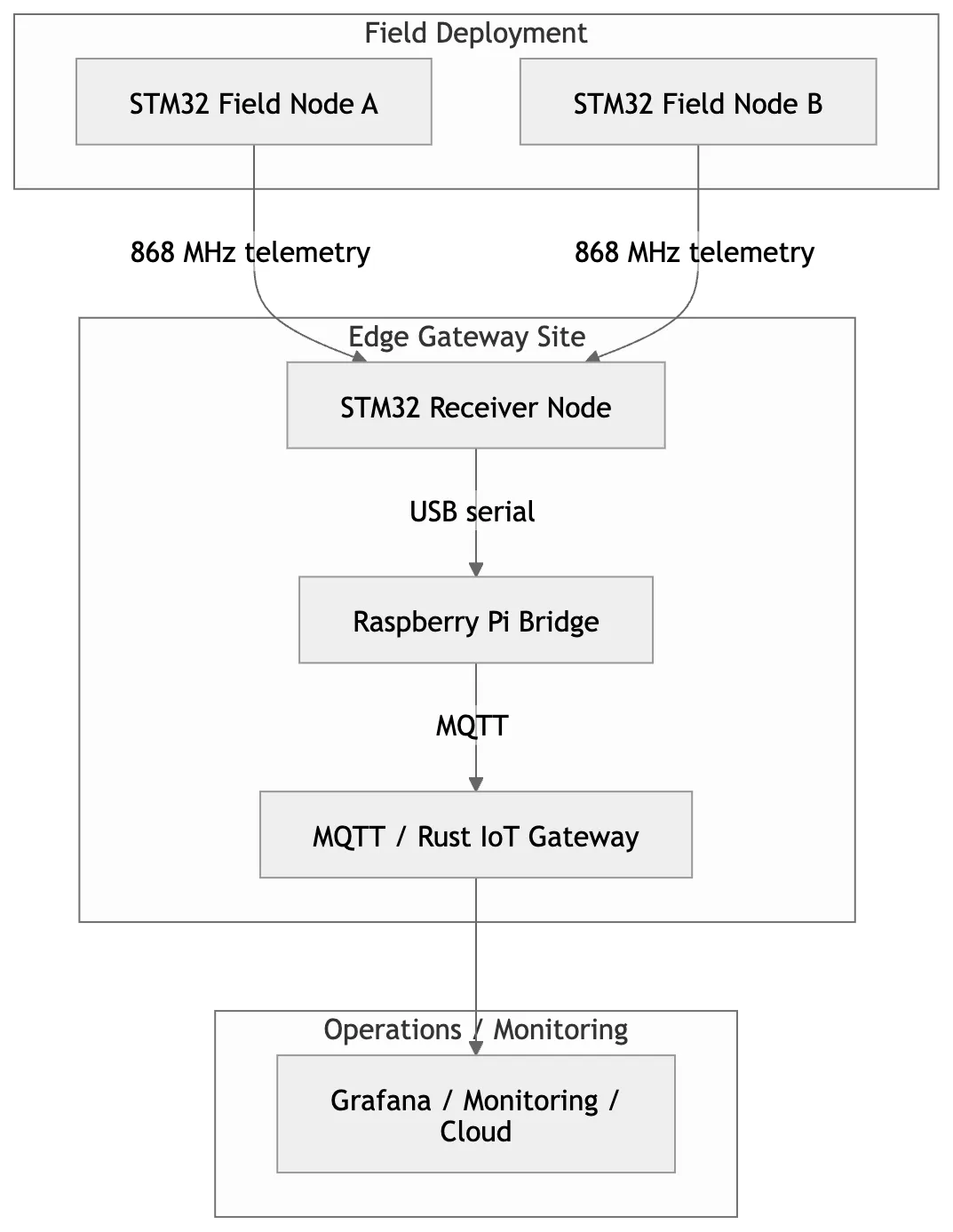
This higher-level view makes the site boundary clearer: field nodes live out in the deployment area, while the receiver, Raspberry Pi bridge, and gateway stay together at the collection point before telemetry moves into monitoring or cloud systems.
What I want to validate before calling this a success
The interesting questions are not “does one packet arrive?” The interesting questions are whether the setup is good enough to trust once the placement becomes more realistic.
These are the checks I care about first:
- Whether
868 MHzgives cleaner reach than Wi-Fi for the building placements I actually care about. - Whether per-device identity stays clean from the radio transmitters through the receiver and into the Raspberry Pi.
- Whether the serial bridge can run long enough to collect useful telemetry without introducing avoidable ambiguity.
- Whether retries, drops, and timing gaps stay understandable once the transmitters are no longer sitting close to the collection node.
- Whether the same path is realistic enough to start experimenting with staged over-the-air update delivery later.
That last point needs a careful caveat: I am not claiming over-the-air updates are already solved on this radio path. What I want first is a believable transport baseline. Once I understand how the link behaves, then it becomes worth testing what firmware chunking, retries, acknowledgements, and receiver-side coordination would be needed for OTA work.
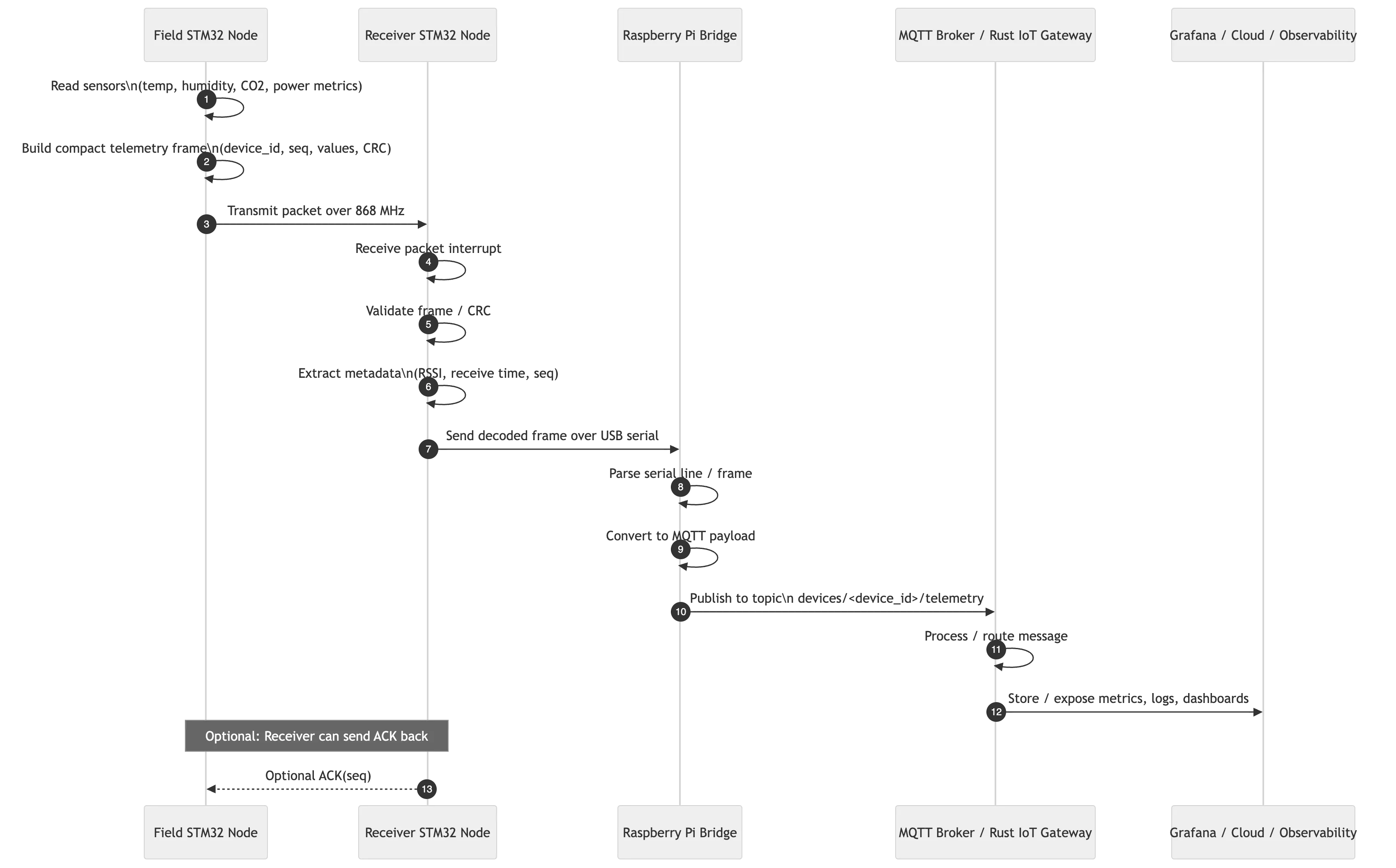
The sequence view is useful because it shows where the observability and failure questions will sit: packet creation on the field node, decode and metadata extraction on the receiver, serial framing on the Raspberry Pi, and eventual publish into the gateway path. The optional ACK path is one of the later details I want to test rather than assume.
Why this matters for better field demos and audit work
This is useful to me as a development step, but it also matters commercially.
A stronger field demo creates better proof. Instead of saying a device can publish when everything is close and friendly, I can show how telemetry behaves when device placement, radio reach, and collection boundaries start to look more like reality.
That helps in a few ways:
- It makes the telemetry story more believable.
- It exposes where the collection path becomes fragile.
- It creates a better test bed for comparing transport choices.
- It gives future audit work a more realistic slice to inspect across device, radio, receiver, and gateway boundaries.
For teams dealing with building telemetry, plant-room placement, or awkward coverage areas, this is often where the useful architecture questions start. The question is not just how to get data into the cloud. The question is how to keep the collection path trustworthy before the environment starts fighting you.
If this planning note is the right slice for your team, the next Combotto reads that usually pair well with it are the three-device gateway runtime proof, the Raspberry Pi 5 gateway migration notes, and the broader IoT architecture audit checklist.
What I will share once the demo is running
Once this setup is live, the useful follow-up is not a victory post. It is the evidence:
- what the real placement looked like
- how far the transmitters could be moved before the link got noisy
- what the receiver-to-Pi serial bridge looked like under longer capture windows
- what broke first
- whether OTA experiments over the same path are practical or need a different delivery design
That is the point where the demo stops being a plan and starts becoming field proof.
Useful references for this setup
- STM32
B-L475E-IOT01ADiscovery kit product page SPSGRFSub-GHz module product page- ST proprietary Sub-1 GHz documentation hub
X-NUCLEO-IDS01A4SPSGRF-868expansion board reference- Three-device Raspberry Pi gateway field demo
- Moving the gateway to Raspberry Pi 5
- 3D printed enclosure notes for the
B-L475E-IOT01A2 - IoT architecture audit checklist
Related next steps
If you are weighing radio reach, telemetry trust, or OTA feasibility, start by testing the path that already feels weakest in the field.
The right first step is usually not a huge platform rewrite. It is a bounded look at the device placement, transport boundary, receiver behavior, and collection node that your team already trusts least.